


Please Leave Us A Message

Haoyong Automotive Controls
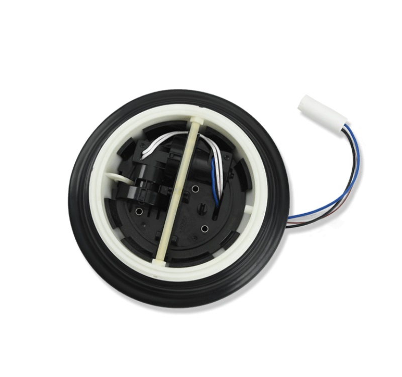
Large Mirror Driver For Rear View Mirror: Technical Overview and Applications
The Large Mirror Driver (LMD) for rear view mirrors is an advanced electro-mechanical system designed to provide precise control over mirror positioning in automotive and industrial applications. These systems typically incorporate high-torque motors (ranging from 12-24V DC with 5-15 N·m torque output), position sensors with ±0.5° accuracy, and durable gear mechanisms rated for 50,000+ actuation cycles. Modern LMD units feature CAN bus or LIN network compatibility with response times under 200ms for full range of motion.
Large mirror drivers operate within a voltage range of 9-36V DC, with typical current draw of 2-5A during operation and standby current below 10mA. High-end models feature brushless DC motors with efficiency ratings exceeding 85%, capable of moving mirrors weighing up to 3.5kg through a 120° horizontal and 60° vertical range.
Designed for harsh conditions, LMD systems meet IP67 waterproof ratings and operate reliably in temperature ranges from -40°C to +85°C. Vibration resistance meets ISO 16750-3 standards for automotive applications, withstanding 5-500Hz random vibration profiles at 1.5g RMS.
Advanced units incorporate 16-bit resolution encoders for position feedback and PID control loops with adjustment rates up to 1kHz. Communication protocols include CAN FD (up to 5Mbps), LIN 2.2A, and PWM control signals (100-1000Hz).
Commercial Vehicles: For large side mirrors on trucks and buses, requiring 30-50% larger actuation force than passenger car systems
Construction Equipment: Heavy-duty versions with impact-resistant housings for excavators and loaders
Emergency Vehicles: Special configurations with fail-safe positioning for fire trucks and ambulances
Security Systems: For controlling mirrors up to 1.5m diameter in surveillance installations
Solar Concentrators: Precision mirror alignment in concentrated solar power (CSP) plants
Aerospace: Custom units for aircraft rear-view systems with military-grade connectors (MIL-DTL-38999)
For optimal performance, conduct quarterly inspections including:
Check electrical connections for contact resistance below 50mΩ
Verify mechanical play remains under 0.5mm at mirror edge
Test full range of motion for consistent speed (typically 15-30°/sec)
Apply silicone-based grease (ISO VG 100-150) to gear mechanisms every 2 years or 25,000 cycles. Avoid petroleum-based lubricants which may degrade plastic gear components.
Monitor for:
Voltage fluctuations beyond ±10% of nominal rating
Current spikes exceeding 150% of rated maximum
Ground continuity with resistance below 0.1Ω
When servicing mirror drivers, always disconnect power and follow lockout/tagout procedures. The stored energy in these systems can produce pinch forces exceeding 100N even when powered off.
Modern LMD systems may require periodic firmware updates to:
Improve PID control algorithms
Add new communication protocol support
Implement advanced diagnostic routines
If position accuracy degrades beyond ±1°:
Recalibrate using manufacturer-specified procedure
Check for mechanical binding (resistance > 2N·m)
Verify encoder signal integrity (noise < 50mVpp)
Abnormal sounds may indicate:
Worn gear teeth (inspect for >0.2mm wear patterns)
Dry bearings (listen for frequencies above 5kHz)
Loose mounting hardware (check torque specs: typically 4-6N·m)

Mr. Hansol Kim