
Most plastic gears used in compact automotive actuators are produced through injection molding, although machining may be used for prototypes, small production runs, or specialized applications. Successful manufacturing requires more than producing the correct gear shape. Material selection, mold design, processing conditions, dimensional inspection, and assembly verification must work together to ensure consistent gear engagement under the actuator's actual operating loads.
Why Plastic Gears Are Used in Automotive AC Actuators
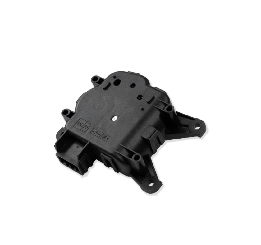
An AC actuator typically contains a small electric motor and a reduction gear train that increases usable output torque while reducing rotational speed. Plastic gears help achieve this reduction in a compact package, making them suitable for HVAC blend Door Actuators, mode Door Actuators, and recirculation Door Actuators.
Compared with metal gears, appropriately designed plastic gears can offer lower weight, reduced operating noise, good corrosion resistance, and economical high-volume production. Their material properties can also provide useful friction and vibration characteristics. These advantages are particularly valuable in passenger vehicles, where HVAC components must operate quietly within a confined dashboard assembly.
However, plastic gears have limitations. Their stiffness, strength, and dimensions can change with temperature, and their performance depends on the selected polymer, gear geometry, applied load, and manufacturing quality. Excessive loading may cause tooth deformation or fracture, while repeated operation can gradually increase backlash and wear.
Material selection must therefore reflect the actual application. Depending on the design, manufacturers may consider engineering polymers such as POM (polyoxymethylene), PA (polyamide), or other suitable materials. The appropriate choice depends on required strength, friction, wear resistance, dimensional stability, moisture sensitivity, operating temperature, and compatibility with any specified lubricant. No single plastic is automatically best for every AC actuator gear.
Material Preparation and Gear Design Before Molding
Plastic gear quality begins before the molding machine starts operating. Engineers must establish the gear's module, tooth count, pressure angle, pitch diameter, face width, shaft interface, and required clearance based on the transmission design. These characteristics determine how the gear meshes with adjacent gears and how effectively it transfers motor torque to the actuator output shaft.
The gear geometry must also account for the operating environment. A gear designed for a low-load mechanism may not withstand the repeated forces experienced by an actuator that moves a door against significant resistance. Engineers need to consider the expected torque, movement frequency, temperature range, available space, and required service life when selecting the gear dimensions and material.
Resin preparation is another important control point. Certain engineering plastics, particularly moisture-sensitive materials such as polyamide, may require controlled drying before molding. Excess moisture can cause processing defects and degrade material properties, depending on the resin and processing conditions. Manufacturers should follow the resin supplier's drying specifications rather than applying the same preparation procedure to every material.
Material traceability is equally important for mass production. Recording resin grades, supplier batches, drying conditions, and relevant processing data helps manufacturers investigate differences in dimensional stability, mechanical performance, or wear between production lots.
How Injection Molding Produces Precision Plastic Gears
Injection molding is widely used because it can produce large quantities of small, complex gears with repeatable geometry and relatively short cycle times. Plastic resin is heated until it reaches a suitable flow condition, injected into a precision mold cavity, packed under controlled pressure, cooled, and ejected after sufficient solidification.
For a plastic gear, the mold cavity defines the tooth profile, pitch, root geometry, hub, bore, and other functional features. Because the teeth directly determine how the gear engages with its mating component, mold accuracy and cavity condition are critical. Wear, damage, or contamination in the mold can affect tooth geometry and create defects that are difficult to correct during assembly.
Processing conditions also influence the final dimensions. Melt temperature affects material flow, while injection and packing conditions influence cavity filling and shrinkage. Cooling conditions determine how uniformly the part solidifies. If these variables are poorly controlled, the gear may develop warpage, sink marks, incomplete teeth, dimensional variation, or internal stress.
These defects can affect performance in different ways. Incomplete tooth formation may prevent smooth engagement, while warpage can cause uneven contact across the gear face. Uneven shrinkage around the hub or bore may affect shaft fit and concentricity. Excessive dimensional variation can create inconsistent backlash between otherwise identical actuator assemblies.
Manufacturers should establish a stable molding window for the specific resin, mold, and gear design. This includes controlling relevant temperatures, injection speed, packing pressure, cooling time, and material preparation. Process optimization should be supported by dimensional measurements and functional testing rather than relying exclusively on visual inspection.
How Gear Accuracy Affects Torque, Noise, and Backlash
The performance of a molded plastic gear depends on more than its external appearance. Tooth profile, pitch accuracy, concentricity, and the alignment of mating shafts determine how loads are distributed during rotation.
Backlash refers to the clearance between mating gear teeth. A certain amount is necessary to accommodate manufacturing tolerances, thermal expansion, and smooth movement. However, excessive backlash can produce delayed output response when the motor changes direction, reducing positioning consistency and potentially creating clicking noises.
Insufficient clearance can be equally problematic. If the gears mesh too tightly, friction increases and the motor requires more torque to drive the transmission. This can raise current consumption, generate additional heat, and accelerate wear. For this reason, reducing backlash as much as possible is not an appropriate universal manufacturing target. The objective is to maintain the designed clearance across the expected operating conditions.
Concentricity is another important characteristic. If a gear's rotational center does not align properly with its bore or shaft, the effective engagement may vary as the gear rotates. This can produce periodic changes in friction, noise, and transmitted torque. Similarly, poor tooth geometry may concentrate contact forces on a small area, increasing local stress and the risk of premature wear.
Manufacturers should therefore evaluate gear dimensions against engineering drawings and assess the assembled transmission under representative conditions. Checking only the outside diameter cannot establish whether a gear will mesh correctly, transmit the required torque, or operate quietly over its intended service life.
Post-Molding Inspection and Functional Quality Control
Inspection should focus on characteristics that directly influence the gear's function. Visual checks can identify flash, incomplete filling, surface damage, contamination, and obvious molding defects. However, these checks should be combined with dimensional inspection because visually acceptable gears may still fall outside critical tolerances.
Depending on the design and production volume, manufacturers may use optical measurement systems, profile measurement equipment, dedicated gauges, or coordinate measuring equipment to verify critical dimensions. Relevant checks may include tooth geometry, pitch diameter, bore dimensions, gear thickness, runout, and concentricity. The inspection method should match the characteristic being measured and the required tolerance.
Dimensional inspection alone does not confirm transmission performance. A gear may meet its individual dimensional requirements but still behave poorly when paired with another gear if tolerance accumulation, shaft positioning, or housing deformation changes the assembled center distance. Assembly-level verification is therefore essential.
Functional checks can evaluate rotational smoothness, gear engagement, backlash, noise, and output movement. Where the actuator specification requires it, torque or load